Figure 1: Cross-sectional view of a heat pipe embedded radial heat sink.
In light-emitting diodes (LEDs), 70 percent to 80 percent of the applied electrical power is converted to waste heat. If this thermal energy is not properly dissipated, the resulting high operating temperatures lead to reduced brightness, shift in wavelength (color), and reduced life. Optical requirements impose the heat to be extracted through circuit boards designed to balance contradictory thermal management and electrical isolation functions [1-5]. In most general lighting applications, the heat must be ultimately be dissipated through natural convection heat sinks (where radiation may play a significant role) due to acoustic noise restrictions [6-14]. However, the thermal management requirements of emerging high intensity LED lighting products often exceed the practical limits of these passive cooling strategies. In the broader electronics cooling industry, heat pipes have been effectively applied as a means to extend the application window of passively cooled heat sinks through heat spreading enhancement. Although the general guidelines for integrating heat pipes in broader electronics cooling applications still apply to LEDs, their unique thermal requirements require adaptation in the implementation of heat pipes. This article explores the implementation and benefits of heat pipes in natural convection heat sinks and circuit boards for LED applications.
Although each LED may only dissipate a few watts of thermal energy, the small package footprint results in high heat fluxes. Despite heat spreading in the LED packages and circuit boards, these heat fluxes remain significant as the heat is dissipated across the various thermal interfaces between the LED package, circuit boards, and attached heat sinks [15-19]. By embedding heat pipes directly into circuit boards, the thermal interface between the circuit board and heat sinks can be minimized while heat spreading can be enhanced. At the heat sink level, heat pipes may be able to reduce the volume for natural convection heat sinks by 10 percent to 30 percent. Further, the luminaire design may dictate a remote heat sink due to other design considerations, such as aesthetics. In these cases heat pipes enable thermal connection of the remote heat sink to the LED circuit board package with minimal thermal gradient.
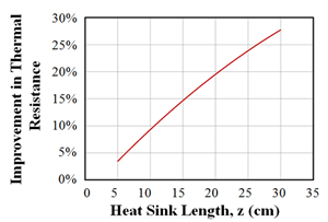
Figure 2: Net percent reduction in thermal resistance (including the heat sink conduction and convection resistances) between the embedded heat pipe and baseline aluminum case as a function of heat sink length and heat transfer coefficient. Note: At each point on this chart,a finite element analysis simulation was performed on identical form factor aluminum and heat pipe embedded aluminum heat sinks (8mm embedded heat pipe, θ=18° (20 fins), 1.27 mm thick fins, w=22.2mm, and d =19.1mm) at various heat sink lengths and prescribed heat transfer coefficients.
NATURAL CONVECTION HEAT SINKS
Heat pipes can be effectively embedded in a variety of heat sink form factors to improve conductive heat spreading. To clearly illustrate the benefits of using heat pipes, a radial heat sink with a heat pipe embedded in the core is chosen as a model case as illustrated in Figure 1. In general, heat pipes tend to have increased benefits as the length (z) of the heat pipe is increased. This is attributed to the low thermal resistance of the heat pipe’s vapor core, which is often negated when compared to other thermal resistances in the system. As a result, the heat pipe’s thermal resistance does not change significantly as the heat sink length is increased. To demonstrate this point, thermal finite element analysis was performed on a typical aluminum extrusion radial heat sink with and without embedded heat pipes (see dimensions in Figures 1 and 2). Heat was applied in a 1cm2 circular region on one side of the base of the heat sink. In a series of simulations, the length of the heat sink was increased while prescribing a heat transfer coefficient associated with natural convection (10 W/m2K). Radiation was not considered in the calculations. The simulation results are summarized in Figure 2, which shows the net reduction in thermal resistance (including the heat sink conduction and convection resistance) between the embedded heat pipe and baseline aluminum case. The improvement with heat pipes approaches 30 percent for heat sinks less than 30 cm long.
Figure 3: IR images and photographs of heat pipe embedded radial heat sinks with direct (left) and remote (right) attachment of the heat source (both scales are set between 70°C and 80°C)
The results of Figure 2 are indicative of the performance improvement when the circuit board is directly connected to the base of the heat sink. Heat pipes show more dramatic improvement when the heat sink is remotely located from the circuit board. Figure 3 shows an infrared (IR) image of two heat pipe heat sinks operating in natural convection conditions with 30 Watts of applied heat. A FLIR A655sc camera with +/-2°C accuracy, 640 x 480 resolution, and a spectral range of 7.5μm to 14μm was used. All surfaces on the heat sink were coated with Medtherm optical black coating (specified to a 0.95 average absorptance over a 0.3 μm to 15μm spectral range). The photograph on the left shows the thermal gradient in a 30 cm long heat sink (the other dimensions are identical to those simulated in Figure 2). The increased thermal gradient near the base of the heat sink is noticeably higher than the opposite side of the heat sink. This is attributed to the evaporator thermal resistance of the heat pipe that must be overcome before heat is transferred into the highly conductive vapor core. After the heat is acquired in the first 10 cm of the heat sink’s length, the heat sink is nearly isothermal due to the low thermal resistance of the heat pipe vapor space. On the right, the same heat sink is remotely attached to the heat source. The heat pipe clearly demonstrates the transport of heat isothermally from the heat source to the heat sink and apply even distribution of heat to the heat sink. A slight increase in temperature is measured across the heat sink (< 0.5°C), due to the sensible heating of air rising through the heat sink.
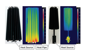
Figure 4: Photograph of metal core printed circuit board with heat pipes soldered into the metal core of the circuit board.
METAL CORE PRINTED CIRCUIT BOARDS
Heat pipes can also be applied at the circuit board level to improve heat spreading performance [20]. There are several strategies for improvement. One strategy is to fully contain the heat pipes within the printed circuit board, as shown in Figure 4. If the ratio of the heat source to circuit board areas is sufficient, this can be an effective way to improve heat spreading at the board level while requiring minimal design changes to the lighting system. Figure 5 shows an IR image of a fully integrated LED/ circuit board/heat pipe assembly during operation.
Another closely related implementation strategy is to simply extend the heat pipe from the circuit board and directly attach the heat pipes to a heat sink. By directly connecting the circuit board to a heat sink using heat pipes, the thermal interface between the circuit board and heat sink is avoided. The improvement in thermal performance is very application specific, and depends on many of the factors described in the natural convection heat sink discussion.